Current status of Project Work
WIRC-POL
Optomechanical Design Support for Polarimetry upgrade| Chuck H. is handling mods to filter wheel for GRISM & PG and new H2_RG mounting and related dewar mods. Some related files: Chuck H. WIRC-POL SOW: SOW_Chuck_Henderson_6_17_16.docx Schedule of WIRC-POL optomechanical upgrades (basis for CH SOW): WIRC-POL_schedule_6_17_16.xlsx |
Precision Cryo dewar and Telic optics drawings are partially converted to SW CAD models in the vault under:WIRC->WIRC-POL->WIRC-POL Preliminary Design->and WIRC->WIRC-POL->WIRC-POL Preliminary Design->COLD-COL-WIRC-OPTICS.SLDASM Precision Cryogenics 2-D hardcopy drawings were scanned into file: PC_WIRC_Drawings.pdf |
| Task | Status |
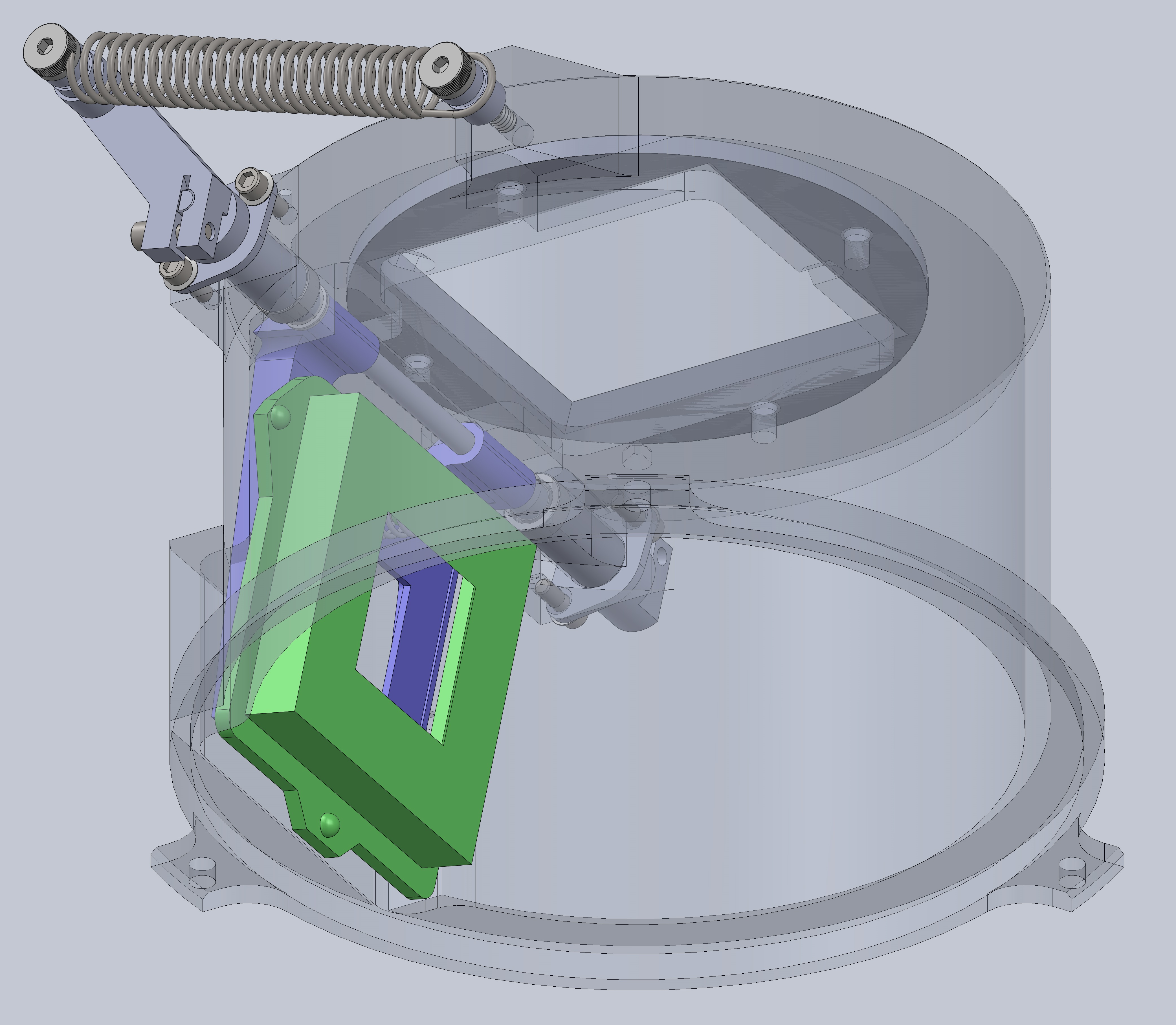
| Two-position focal plane mask for: 1. full-FOV (current configuration) 2. reduced FOV (reduce background behind spectro/polarimetric traces) |
Bi-stable Mechanism preliminary design complete in the SW Vault under: WIRC->WIRC-POL->WIRC-POL Preliminary Design->06_30_16FieldStop mechanism.SLDASM Mechanism actuator, either push pull solenoid or stepper motor (precise actuation unnecessary due to bi-stable design) is still required. Mechanism image: 06_30_16Field_stop_mechanism_transp.JPG |
| Zemax modeling for verifying optomechanical design decisions (e.g.,* WIRC-POL_PG_AOI_7-8-16_weekly_meeting.pdf : Pol. Grat AOI Zemax ) | Current .zmx for WIRC-POL upgrade 4quadrant_WIRCPOL_sequential.zmx : originally an interim version until IUCAA model is provided (still awaiting) |
SED Machine
Instrument stability upgrades: Initial work was done to address the problem of shifting of the spaxel locations and spectral trace separation in the IFU images leading to failure of the data reduction pipeline to produce a data cube and extract reliable spectra. The shifting has occurred repeatedly at intervals of about 2 -3 weeks and shows signs of occurring as both a modest gradual shift with time (intervals of weeks) as wells as isolated, larger rapid (overnight) shifts. One source of this shifting that became evident was rotation of the optics barreled axially housing the SEDM collimator optics and lenslet array. These optics are just upstream of the SEDM prisms and the housing was originally held into a vee-block mounting by tension springs - mounting which allowed it to be easily rotated, and slightly shifted axially, by hand. Example_of_SEDm_spaxel_shift.pdf includes a progression of IFU images shown as overlying contour plots to highlight shift of spaxel location with time relative to a reference image. These P60 dome images were obtained over a period of about two weeks between two adjustments of the collimator barrel required to correct the restore its proper orientation. An explanation of the alignment procedure is shown in SEDM_collimator_rotation.pdf To prevent this loss of lenslet alignment, the tension springs used to hold the collimator barrel in place were replaced with split clamps. These clamps were intended as somewhat of an interim fix that could be installed with minimal disassembly of the instrument and without interruption of nightly observations. Following installation of the clamps a load cell force sensor was used to apply a 14lbf load (about 2 times the weight of the optics barrel) to the barrel opposite a dial indicator to measure any displacement. Displacement under the applied load was less than 3 microns which is within the observed fluctuation of the indicator readout with no load applied. Notes/pictures describing the installation and tests are in SEDM_collimator_clamp_replacement.pdf . Camera optics downstream of the SEDm prisms are mounted in a similar vee-block/tension spring arrangement. Replacement clamps like those installed on the collimator have also been made for these camera optics, but have not been implemented because the procedure required to install them would require further SEDM disassembly and downtime.HCST
Design/Specification of optic mounts, mechanisms, optical enclosures A Solidworks model including the most current optics layout with mounts and mechanisms (a good resource for generating a BOM) is in the SW vault under HCST->HCST CAD MODELS->HCST Preliminary Design->HCST 20160405A.SLDASM Work was done to develop a mount for the Boston Micromachines (BMM) Kilo-DM that would be less susceptible to acoustical vibrations to which Kent W. had found them to be susceptible. An initial design was based on direct rigid mounting to the ZIF socket to which the DM package attaches. This design was thought to be an improvement over the stock mount with attachment points only on the DM circuit board - an approach that was deemed susceptible to the transfer of acoustical vibrations excited in the circuit board to the DM. BMM did not explicitly discourage the custom mount design but did indicate that it would void the warranty primarily because it could potentially damage the ZIF socket. Details from the email exchange with BMM are here:BMM_Kilo-DM_exchange.pdf . It also includes additional details about how the ZIF attaches to the PCB which make the plan of direct-mounting to the ZIF seem less appealing.ZTF Documentation
Assembly of Documents into binder Alternative for greater file access flexibilityOther
Zemax model (), SolidWorks model() and Summary () related to check whether the PTF Shutter might work for WaSP. Zemax model () , and Summary () related to check if NESSI can be configured for PG -- SethWieman - 08 Jul 2016

| I | Attachment | History | Action | Size | Date | Who | Comment |
|---|---|---|---|---|---|---|---|
| |
06_30_16Field_stop_mechanism_transp.JPG | r1 | manage | 1363.0 K | 2016-07-11 - 05:59 | UnknownUser | Image of the WIRC-POL field stop mechanism |
| |
4quadrant_WIRCPOL_sequential.zmx | r1 | manage | 126.3 K | 2016-07-08 - 23:17 | UnknownUser | WIRC-POL .zmx file |
| |
BMM_Kilo-DM_exchange.pdf | r2 r1 | manage | 1062.9 K | 2016-07-11 - 23:17 | UnknownUser | Email discussion with BMM about the modified Kilo-DM mount |
| |
Example_of_SEDm_spaxel_shift.pdf | r1 | manage | 1502.3 K | 2016-07-11 - 05:05 | UnknownUser | Progression of IFU images showing loss of lenslet alignment |
| |
PC_WIRC_Drawings.pdf | r1 | manage | 6226.6 K | 2016-07-11 - 04:20 | UnknownUser | |
| |
SEDM_collimator_clamp_replacement.pdf | r1 | manage | 468.9 K | 2016-07-11 - 05:56 | UnknownUser | Collimator barrel clamp replacement notes |
| |
SEDM_collimator_rotation.pdf | r1 | manage | 755.4 K | 2016-07-11 - 05:09 | UnknownUser | Notes describing an alignment done on the SEDm collimator barrel to restore lenslet alignment |
| |
SOW_Chuck_Henderson_6_17_16.docx | r1 | manage | 15.8 K | 2016-07-08 - 23:28 | UnknownUser | Chuck Henderson SOW for WIRC-POL upgrade |
| |
WIRC-POL_PG_AOI_7-8-16_weekly_meeting.pdf | r1 | manage | 514.0 K | 2016-07-08 - 23:05 | UnknownUser | Pol Grating AOI Zemax |
| |
WIRC-POL_schedule_6_17_16.xlsx | r1 | manage | 33.0 K | 2016-07-08 - 23:38 | UnknownUser | Schedule basis for Chuck H SOW |
Topic revision: r8 - 2016-07-12 - SethWieman

|
|
|
|
Ideas, requests, problems regarding TWiki? Send feedback