MSIM STARTUP
- Open MSIM Camera software and select Test mode
- Open MSIM Main software and select Test mode. All commands will be sent from this MSIM instance.
Connect Motors
- Open Control->Show Motor Control -> SetupConn -> Check that all USB ports are in the selected window and add them if not. Then click ok.
- Optionally may test selected ports to see how many motors are connected (2 per cobra unless gen1)
- Open Control -> Show Motor Control -> Click connect and observe one or more motor ids populate the table
- Open Control -> Show Motor Control -> Load most recent Motor Control Textfile -> Close Dialog
Setup Simulation (necessary for targets)
- Open Simulation -> Show -> Load the most recent Arm Simulation Textfile -> Close Dialog
CAMERA SETUP
From the msim main sequencer, load: D:\DevCodePft\Main\UI\Data\Sequences\Remote_CameraSetup.lst Check that all commands complete successfully (green)Load Bias and Dark Image
- Open main mSim -> Camera -> GetImage -> Load latest Image with same relative exposure time from PfsTests Folder on D:/
- Or run D:\DevCodePft\Main\UI\Data\Sequences\Compute Bias and Dark Images.lst and modify the exposure time to be what you need
REMOTE DESKTOP OF SAGE-PC
- From windows start menu, type in 'Remote Desktop Connection' and open the terminal
- In computer field, input the IP '137.79.69.105'
- Connect using username/password of 'sage'/'cobra'
CENTER METROLOGY
- Execute the appropriate motor map sequence on msim.
D:\DevCodePft\Main\UI\Data\Sequences\GEN2_GEN3_S1_Centers_single_image.lst - Edit and execute the following script in matlab with the correct direcotry containing center metrology images:
\Dropbox\PFSMatlab\Metrology\getImgCentroids.m - There should now be ImageId data structures in your workspace. Save them to the appropriate DropBox results folder.
- Edit and execute the motor map script:
\Dropbox\PFSMatlab\Metrology\makeMotorMap.m - initImage should be the first reference image and then mMapImage should be the center metrology image.
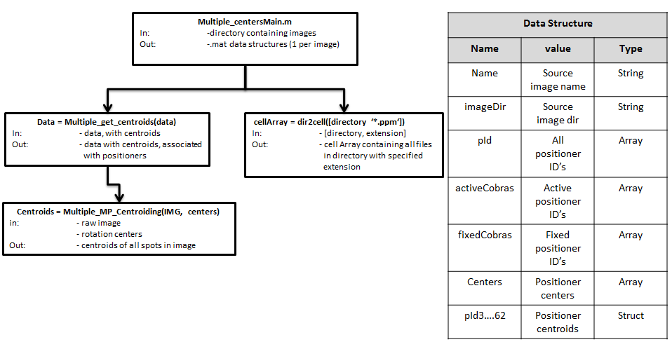
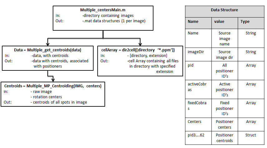
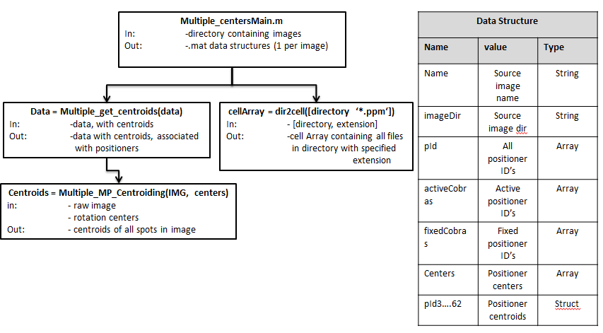
Matlab Metrology
- open Multiple_centersMain.m
- Update the "topdir" variable to the directory containing images for processing.
- Run the script.
- A series of .mat files is generated. Each file contains a data structure that contains the information listed below.


| I | Attachment |
History | Action | Size | Date | Who | Comment |
|---|---|---|---|---|---|---|---|
| |
Matlab_Metrology_tree.PNG | r3 r2 r1 | manage | 32.1 K | 2014-01-28 - 21:34 | UnknownUser | Matlab metrology tree |
Topic revision: r8 - 2014-01-28 - ChazMorantz

Ideas, requests, problems regarding TWiki? Send feedback