

| I | Attachment | History | Action | Size | Date | Who | Comment |
|---|---|---|---|---|---|---|---|
| |
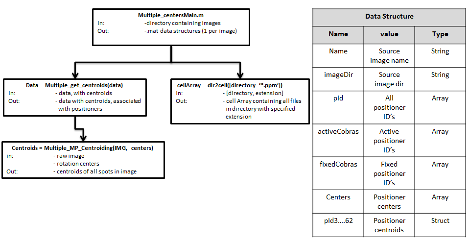
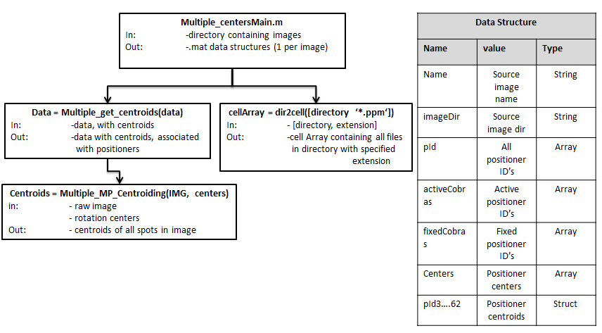
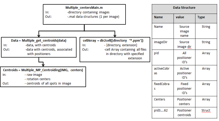
Matlab_Metrology_tree.PNG | r3 r2 r1 | manage | 32.1 K | 2014-01-28 - 21:34 | UnknownUser | Matlab metrology tree |
This topic: Subaru/PFS > WebHome > POSitionerTB > ProtoTB_Procedures
Topic revision: r8 - 2014-01-28 - ChazMorantz
Ideas, requests, problems regarding TWiki? Send feedback